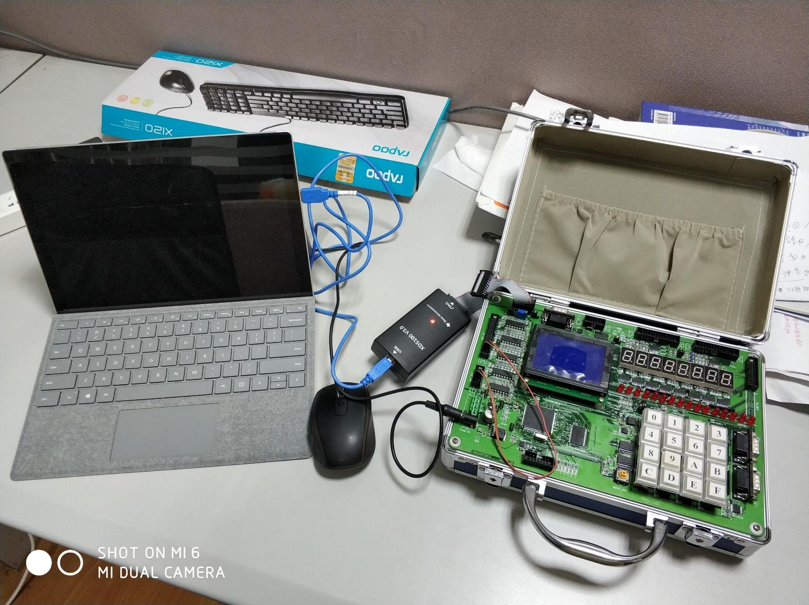
Source code of The Principle & Application of Microcomputer & DSP course labs from ZJU.
Repository url: https://github.com/EduardChou/TMS320F2812-labs
If you are someone involved in the course thinking this repository is not allowed, please PM me or comment, I’ll delete it as soon as possible.
Notes for Compiling
The source code is written in C and should be run in the Code Composer Studio (CCS) 7.2 development environment. The TMS320F2812 demoboard should be connected to the PC running CCS program via USB. Please modify the headers including path of each projects while compiling them.

Expected Results
lab1
The third green light on the left flashes, the fifth green light goes out, and the rest are fully lit.
lab2
The red lights on both sides are illuminated.
Green lights are lit as follows:
-
the 1st one on the left lights for 1 second and goes out for 1 second.
-
the 2nd from the left lights for 0.5 seconds and goes out for 0.5 seconds
-
the 3rd from the left lights for 0.1 seconds and goes out for 0.1 seconds
-
the 4th one on the left lights up for 0.01 seconds and goes out for 0.01 seconds
-
the 5th from the left lights up for 0.005 seconds and goes out for 0.015 seconds.
-
the 6th one on the left is completely black.
lab3
All green lights go out and red lights are lit according to the following rules:
-
the first one on the left lights up for 1 second and goes out for 1 second; the first one on the right lights up for 0.5 seconds and goes out for 0.5 seconds.
-
the 6th one on the left lights for 1 ms and goes out for 9 ms; the 6th one on the right lights for 9 ms and goes out for 1 ms.
-
the 7th one on the left lights up for 2 ms and goes out for 8 ms; the seventh one on the right lights up for 7 ms and goes out for 3 ms.
-
the 8th one on the left lights up for 3 ms and goes out for 7 ms; the eighth one on the right lights up for 5 ms and goes out for 5 ms.
lab4
The board outputs a digital clock displayed by the digital tubes, the numbers of the clock can be modified by pressing a key, and a timing function is included.
lab5
The board implements the fading blinking of the green and red lights on the development board. By dynamically changing the duty cycle of the PWM wave to adjust the lighting time of the LED in one cycle, due to the high frequency of the PWM wave beyond the resolution of the human eye, it is continuous light in the human eye, and according to the change of the fading duty cycle, it can be expressed as a constant change of the LED brightness.
lab6
Program implements the A/D conversion program and achieves the following.
-
when the voltage is greater than 1.5V, the second red light on the right is on and the other lights are off.
-
when the voltage is less than 0.9V, the second red lamp on the left is on and the other lamps are off.
lab7
The program achieves the following functions.
-
Use the eight-segment digital tube on the target board to design a digital clock with the function of “hour, minute and second”.
-
Use the keys to control the increase or decrease of the time of hours, minutes and seconds.
-
Use the keys to input the numbers directly to change the numbers displayed on the clock.
-
Use the keys to select the function switch.
-
Display the A/D conversion result of the input voltage value on the eight-segment digital tube.
-
Indicate the input voltage magnitude by the six lamps of GPIOF, i.e:
-
the duty cycle of the first lamp for input voltage U is U/3.
-
the duty cycle of the sixth lamp brightness is (3-U)/3.
-
the brightness of the remaining four lamps is arranged in an equal-difference manner.
-
lab8
The exam.
The program displays the clock on the development board. At the same time, 6 green lights display the group number (9) in binary, the 3rd red light on the left side goes out for odd seconds and comes on for even seconds, and all other red lights go out.